
BCS041 Ignou Solved Question Paper
BACHELOR OF COMPUTER APPLICATIONS (BCA) Term-End Examination, 2019
BCS-041 : FUNDAMENTALS OF COMPUTER NETWORKS
1. (a) How the number of turns in UTP cable is related to its performance ? Why shielding of cable is required ? Explain briefly.
Sol: The wires in UTP cable in each pair are twisted around each other. UTP cable relies solely on the cancellation effect produced by the twisted wire pairs to limit signal degradation caused by electromagnetic interference (EM!) and radio frequency interference (RFI). To further reduce crosstalk between the pairs in UTP cable, the number of twists in the wire pairs varies. UTP cable must follow precise specifications governing how many twists or braids are permitted per meter of cable.
The pairs are twisted to provide protection against crosstalk, and noise generated by adjacent pairs. When electrical current flows through a wire, it creates a small, circular magnetic field around the wire. When two wires in an electrical circuit are placed close together, their magnetic fields are the exact opposite of each other. Thus, the two magnetic fields cancel each other out. They also cancel out any outside magnetic fields. Twisting the wires can enhance this cancellation effect
Shielding around the cable to further protect it from external interference. The shielding further reduces the chance of crosstalk but the shielding increases the overall diameter and weight of the cable.
(b) Explain how a wireless network is configured.
Sol: The steps to configure a wireless network are given below :
1. Switch on the computer and Access point
2. Activate the wireless network mode of computers
3. Connect Access point to the computer through straight cable
4. Open the web browser
5. Type the IP address of Access point given with the access point at the place where URL is typed, and press enter
6. Access point window will be opened
7. Generate SSID and Password from the opened Access point window
8. Ping the access point through you computer by typing “ping ip address of access point” from the command prompt, successful response assures the connectivity
9. Now you may disconnect the wired connection between the computer and the access point. 10. Activate the wireless network mode of other computers in the near vicinity of the access point, they will automatically detect the network.
11. Once the network is detected, to get connected to that wireless network, just select the respective network and it will ask for the SSID code and Password.
12. Provide the assigned SSID code and password, press enter and you are connected to that network.
13. Now you may assign the respective ip addresses to the computer systems connected to the access point and use the same process as discussed above to verify the connectivity among the computers
(c) Briefly explain X.25 architecture with the help of a diagram.
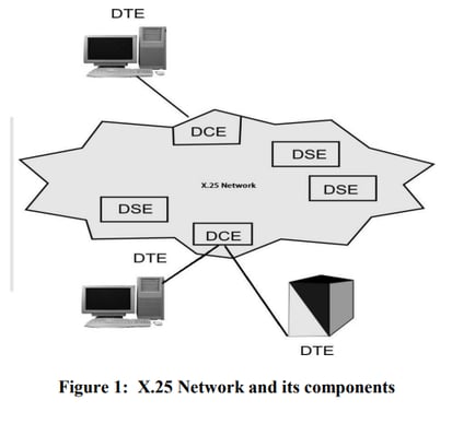
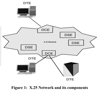
Sol: X.25 is an old standard protocol suite for packet based wide area network. At present X.25 protocols has been replaced by other better and less complex protocols of TCP/IP suit however, the service is still in use in some places.
X.25 does not specify how the network operates internally; it specifies only the interface between public switched networks and the users. As shown below in the figure DTE (data terminal equipment) is a user/subscriber, DCE (data communications equipment) is a device between a network and user, in general it is MODEM device, DSE are nothing but data switching exchanges in a packet switching based WAN.
X.25 is specified on 3 layers:
Physical layer
Data link layer
Network layer
X.25 Network provides the means for these users (DTE) to communicate with each other. In the context of X.25 Data link and Network Layers, an X.25 DCE is the local network node to which the DTE is connected. The X.25 protocol defines the rules for the communication between the DTE and the DCE. You may again note that communication within the WAN may be entirely by some other mechanism.
• Physical layer: Specify the physical, electrical and interface between host and network. It also specifies functional and procedural characteristics to control the physical link between a DTE and a DCE. Common implementation is X.21protocol.
• Data link layer: Deal with data transmission over an between user equipment and routers. Error control and flow control are its main responsibilities. This layer consists of the link access procedure for data interchange on the link between a DTE and a DCE.
• Network layer: this layer specify a packet-layer protocol for exchanging control and user data packets to form a packet-switching network based on virtual calls. It has main functions like Addressing, Flow control, Delivery confirmation, etc. Also, it allow to established Virtual Circuit and send packet reliably
X.25 is connection oriented architecture and support switched virtual circuits (SVC) and permanent virtual circuits (PVC). Switched virtual circuits are established on the need basis. SVC is established when a call is made and broken down after the call is completed.
(d) Briefly explain client-server model of network.
Sol: Client/server network operating systems allow the network to centralize functions and applications in one or more dedicated file servers. The file servers become the heart of the system, providing access to resources and providing security. Individual workstations (clients) have access to the resources available on the file servers. The network operating system provides the mechanism to integrate all the components of the network and allow multiple users to simultaneously share the same resources irrespective of physical location.
In a client-server environment like Windows NT or Novell NetWare, files are stored on a centralized, high speed file server PC that is made available to client PCs.
(e) What is TCP's sliding window ? Explain Silly Window Syndrome with the help of a diagram.
Sol: TCP sliding window determines the number of unacknowledged bytes, x, that one system can send to another. TCP’s sliding window is byte oriented. The source does not have to send a full window’s worth of data. The size of the window can be increased or decreased by the destination. The destination can send an acknowledgement at any time.
Silly Window Syndrome
This problem occurs when the sender transmits data in large blocks, but an interactive application on the receiver side reads data 1 byte at a time.
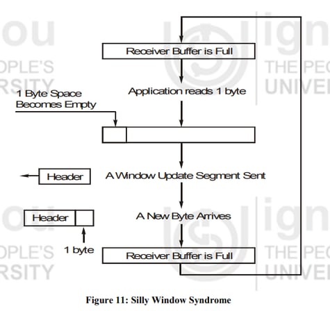
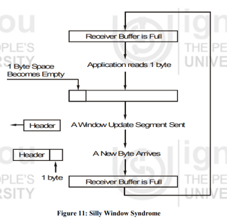
Initially the receiver’s buffer is full so it sends a window size 0 to block the sender.
But the interactive application reads one byte from the buffer, so one byte space becomes empty.
The receiving TCP sends a window update to the sender informing that it can send 1 byte.
The sender sends 1-new byte.
The buffer is full again and the window size is 0. The behavior can continue forever’s.
(f) What is parity bit method for error detection ? Suppose a bit sequence 110001010111 is received. Assume odd parity bit method is used. Find whether received bit sequence is correct or not.
Sol: A binary digit called “parity” is used to indicate whether the number of bits with “1” in a given set of bits is even or odd. The parity bit is then attached to original bits. In this method sender adds the parity bit to existing data bits before transmission. At the receiver side, it checks for the expected parity, if wrong parity found, the received data is discarded and retransmission is requested.
Assume, sender wants to send some bit streams like 001 0101 and 101 0011. If we are using even parity bit method, we will add “0” with the bit stream having even number of 1’s otherwise add “1”. So our bit steams will be changed after adding parity bit as 1001 0101and 0101 0011.
Given: 110001010111
The total number of 1's in the given sequence is 7
Hence odd parity is used the sequence is correct.
2. (a) What is IPV 6 ? Explain its needs. How IPV 6 is better than IPV 4 ?
Sol: IPV 6 is a new addressing system has been devised which is a part of Internet Protocol version 6 (IPv6), which uses 128-bit addresses, means total addresses will be 2^128 . This IPv6 (Internet Protocol version 6) is a revision of the earlier internet Protocol (IP) version 4. IPv6 addresses are consist of eight groups of four hexadecimal digits separated by colons, for example 2001:0db8:85a3:0042:0000:8a2e:0370:7334.
IPv6 is designed to swap the existing IPv4, which is the main communications protocol for most Internet traffic as of today. IPv6 was developed to deal with the long-anticipated problem of IPv4 running out of addresses, some of the reasons and need for implementing IPv6 are following:
• The short term solutions like sub-netting, classless addressing cannot fulfill the massive future demand of address space.
• The internet must accommodate the real-time audio and video transmission with best quality of services.
• Internet protocol must provide the necessary security implementation for some applications.
• There is a need of multicasting in current IPv4, where the transmission of a packet to multiple destinations can be sent in a single send operation.
• IPv4 need a major revision in various issues like privacy, mobility, routing, QoS (quality of services), extendibility and addressing.
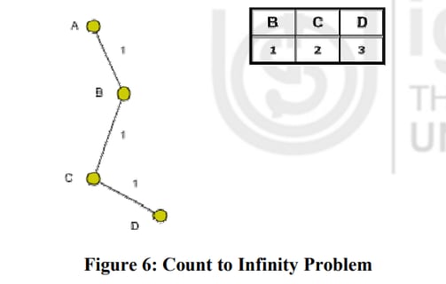
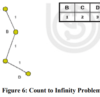
(b) What is count to infinity problem in distance vector routing protocol ? How does it happen ? Explain briefly.
Sol: .Count to Infinity Problem-Distance vector routing has a serious drawback in its receptivity. In particular, it reacts rapidly to good news, but slowly to bad news. Following illustration shows an imagined network and denotes the distances from router A to every other router in the figure 6. Until now everything works fine.
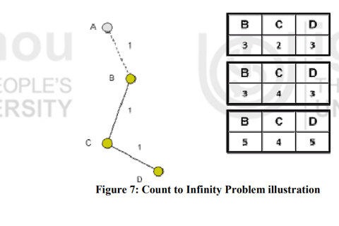
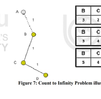
The illustration shows that link (A, B) is broken. Router B observed it, but in its routing table he sees, that router C has a route to A with 2 hops.
The problem is, that router B doesn't know that C has router B as successor in his routing table on the route to A.
That occurs followed count-to-infinity problem. B actualizes his routing table and takes the route to A over router C.
In the below figure; we can see the new distances to A. In C's routing the route to A contains router B as next hop router, so if B has increase his costs to A, C is forced to do so. Router C increases his cost to A about B + 1 = 4. Now we see the consequence of the distributed Bellman-Ford protocol: Because router B takes the path over C to A, it updates its routing table and so on! At the end, this problem is going to immobilize the whole network.
3.(a) What is OSI model ? List all the layers of OSI model and also write two functions of each layer.
Sol: The model is called the ISO - OSI (International Standard Organisation - Open Systems Interconnection) Reference Model because it deals with connecting open systems — that is, systems that follow the standard are open for communication with other systems, irrespective of a manufacturer.
Its main objectives were to allow manufacturers of different systems to interconnect equipment through standard interfaces globally. Allow software and hardware to integrate well and be portable on different systems. The OSI model has seven layers.
The principles that were applied to arrive at the seven layers are as follows:
Each layer should perform a well-defined function.
The function of each layer should be chosen with an eye toward defining internationally standardized protocols.
The layer boundaries should be chosen to minimize the information flow across the interfaces.
A layer serves the layer above it and is served by the layer below it.
The 7 layers of OSI as follow:
Physical Layer: Physical Layer defines functional, electrical and mechanical specifications of signaling, cables, and connectors options that physically link two nodes on a network. sending computer bits from one device to another along the network.
Data Link Layer : The main task of data link layer is to provide error free transmission. It handles node-to-node data transfer, error detection, and flow control.
Network Layer: The network layer ensures that each packet travels from its sources to destination (both in different networks) successfully and efficiently. Is responsible for data routing, forwarding, and addressing.
Transport Layer: The basic function of the transport layer is to accept data from the session layer, split it up into smaller units if need be, pass these to the network layer, and ensure that the pieces all arrive correctly at the other end.
Session Layer: The main tasks of the session layer are to provide:
• Session Establishment
• Session Release – Orderly or abort
• Synchronization
• Data Exchange
• Expedited Data Exchange
Presentation Layer: The presentation layer manages these abstract data structure and converts from the representation used inside the computer to the network standard representation and back. It also performs the task of encryption and decryption.
Application Layer: Application Layer supports functions that control and supervise OSI application processes such as start/maintain/stop application, allocate/deallocate OSI resources, accounting, check point and recovering. It also supports remote job execution, file transfer protocol, message transfer and virtual terminal.
3.(b)What is problem with PSK ? Explain how it may be solved.
Sol: The problem with phase shift keying is that the receiver cannot know the exact phase of the transmitted signal to determine whether it is in a mark or space condition. This would not be possible even if the transmitter and receiver clocks were accurately linked because the path length would determine the exact phase of the received signal. To overcome this problem PSK systems use a differential method for encoding the data onto the carrier. This is accomplished, for example, by making a change in phase equal to a one, and no phase change equal to a zero.
One simple improvement can be made by making a change in phase by 90 degrees in one direction for a one, and 90 degrees the other way for a zero. This retains the 180 degree phase reversal between one and zero states, but gives a distinct change for a zero.
4.(a) What is Packet Switching ? Explain connection less packet switching with the help of a diagram.
Sol: The packet switching works on the principle that the long messages are fragmented into small size units, known as packets. It is these packets that are transmitted instead of the single long message. These packets are now transmitted over the network in the same manner as the messages in message switching.
In the Packet Switching, packetizes the data to transfer and Multiplex it onto the wire. Thus packets from different connections share the same link. The packets are stored and forwarded at every node. Obviously every packet now has to have the source and destination addresses
Connection Less Packet Switching
In this mode of transmission, packets from a source machine to a destination machine are transmitted as per-packet basis, meaning that each packet is transmitted and routed independently from all other packets. So, even if the source and destination machines do not change, routers in the middle may decide to change the routes that different packets follow , resulting in the different packets reaching their destination in a different order from the sender because of the different transmission path length , difference in transmission rates, and the amount of congestion in the different paths.
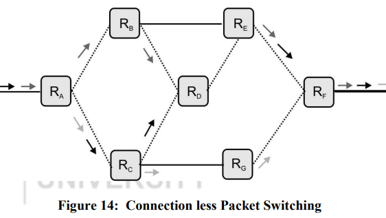
S denotes the source and D denotes the destination. R represents the router, whereas the packets have been shown by the arrow. Three packets are transmitted from the same source machine heading towards the same destination machine. Each route of the network shows the packets that have travelled over it. It is clear that the packets may arrive at the destination machine in an order different from the transmission order.
Since the details of this routing table change with the movement of the packets, the routing of different packets often changes.
The transmission process involves the following steps:
Transmit Packet 1
Transmit Packet 2
……
………..
Transmit Packet N
(b) What are Quality of Services (QoS) of network ? Briefly explain any three parameters of QoS. Also list any two techniques to improve QoS.
Sol: Quality of service (QoS) is the use of mechanisms or technologies that work on a network to control traffic and ensure the performance of critical applications with limited network capacity.
Following are QOS of network
Reliability: Reliability is the ability of a system to perform and maintain its functions in normal conditions as well as under unexpected conditions.
Delay is defined as the time interval elapsed between the departures of data from the source to its arrival at the destination.
Jitter: Jitter refers to the variation in time between packets arriving at the destination.
Bandwidth refers to the data rate supported by a network connection or interface.
Techniques to Improve QOS :
Over Provisioning: An easy solution is to provide so much router capacity, buffer space and bandwidth that the packets just fly through costly.
Buffering: Flows can be buffered on the receiving side before being delivered. Buffering those does not affected the reliability of bandwidth and increases the delay but it smoothes out the jitter.
Scheduling: Packets from different flows arrive at a switch or router for processing. A good scheduling technique treats the different flows in a fair and appropriate manner.
5. Write short notes on the following :
(a) Communication Ports: In computer networking of connection-based communication port is like a medium through which, an application establish a connection with another application by binding a socket by a port number. Addressing the information and the port number, accompanied the data transfer over the network.
The Ports are used by TCP and UDP to deliver the data to the right application, are identified by a 16-bit number present in the header of a data packet. Ports are typically used to map data to a particular process running on a client.
(b)Multiplexing : Multiplexing is a technique that allows multiple signals to be transmitted simultaneously over a single communication channel.
Multiplexing at transport layer occurs in two ways:
Upward -meaning that multiple transport layer connections use the same network connection. Transport layer uses virtual circuits based on the services of the lower three layers. The underlying network charge for each virtual circuit connection. To make well cost-effective use of an established circuit, the transport layer sends several transmissions based for the same destination along the same path by upward multiplexing.
Downward- (meaning that one transport layer connection uses multiple network connections. It allows the transport layer to split a single connection among several different paths to improve throughput. This option is useful when the underlying networks have low or slow capacity.
(c)Authentication and Privacy : Authentication and Privacy refer to the problems of ensuring that communication takes place only between authorized and authenticated users or the right parties without disclosing information to unauthorized users.
Authentication is all about identifying the user and based on his identification, giving access and rights to the user.
Authentication-Identification
ATM, e-banking identifies a user with the help of PIN
Access to e-mail, computer accounts, identifies a user with the help of a password
Access to personal information (e.g., staff or student portal)
Non-computer identification
Bank teller knows you by sight
Bank teller checks your picture against a photo ID
Bank back office compares cheque signature to one on record
All examples of biometric identification.
Computer Identification
How we identify a human to a computer?
Username/Passwords (common),
Token, e.g. ATM card,
Cryptographic protocols,
Combinations, e.g. token and password,
Biometrics, e.g. face recognition, finger prints, and retina/iris scans
Privacy : Handling user privacy and maintaining user security are tough tasks to do. In most of the cases, it is done through a technique called “Cryptography”. Cryptography is defined as a process of conversion of plain and readable text to cipher and (unreadable) text called encryption.
Decryption is the process of converting cipher and unreadable text to plain and readable text (called decryption).
(d) Synchronous and Asynchronous Transmission: Synchronous transmission means both receiver and sender has an agreement (or aware) about timing for the sending data, so that both sender and receiver can coordinate (synchronize) their data signals.
Asynchronous means "not synchronous", or no coordination between sender and receiver before transmission.
The asynchronous transmission uses start and stop bits to signify the beginning bit. For example, if sender wants to send some data "11100001”, it will be appended with the start and stop bit and look like "1 11100001 0". Where, we have assumed that ‘0’ is start bit and ‘1’ is stop bit. Asynchronous transmission works well where the characters are transferred at irregular intervals e.g. data entry from the keyboard.
In case of synchronous transmission, we do not use any start and stop bits, but instead of that clock signal end (clock is built into each end of transmission) is being used for synchronizing the data transmission at both the receiving and sending. A constant stream of bits is sent between the sender and receiver. As clock synchronization may disturbed the possibility of error increases in synchronous transmission